In Part 1 of this series, I introduced this project: I’m building a light show for my office in order to attract people to my office and to offer a creative, motivating outlet for people to learn to code. I spent most of the first post describing the calculations and components necessary to power 900 LEDs all at once. In this post, I’m going to talk about how I built an enclosure to house all of the power distribution components.
Why build an enclosure?
Aside from the fact that it’s fun and makes your project look that much cooler, an enclosure (aka an “electronics project box”) helps keep all of your components organized in a compact space. It allows you to make sure that you don’t get crossed wires, or frayed insulation, or have other problems that could lead to fire, injury, or at best, damaged components. It also makes it easier to debug problems should they arise.
I got a lot of inspiration from this post over at Ponoko.com. They have a lot of pictures of various designs and they explore the pros and cons of making your box out of a variety of materials like plexiglass (acrylic), wood, aluminum, steel, or 3D printable materials like ABS or PLA.
The Outside of the Box
I decided to build my box out of clear acrylic (plexiglass) because it’s relatively inexpensive, looks good, I have some experience working with it, and I have access to a laser cutter at the maker space at my university. I started out by sketching my idea out on paper. Then I spent maybe 15 hours drawing the top, bottom, and sides using Adobe Illustrator. Although I’m not very proficient with Illustrator, with enough time, I can generally figure out how to do all of the things that I want. I really like how precise I am able to get things with Illustrator, as I can specify dimensions down to fractions of a millimeter. Here are some screenshots of my finished designs:
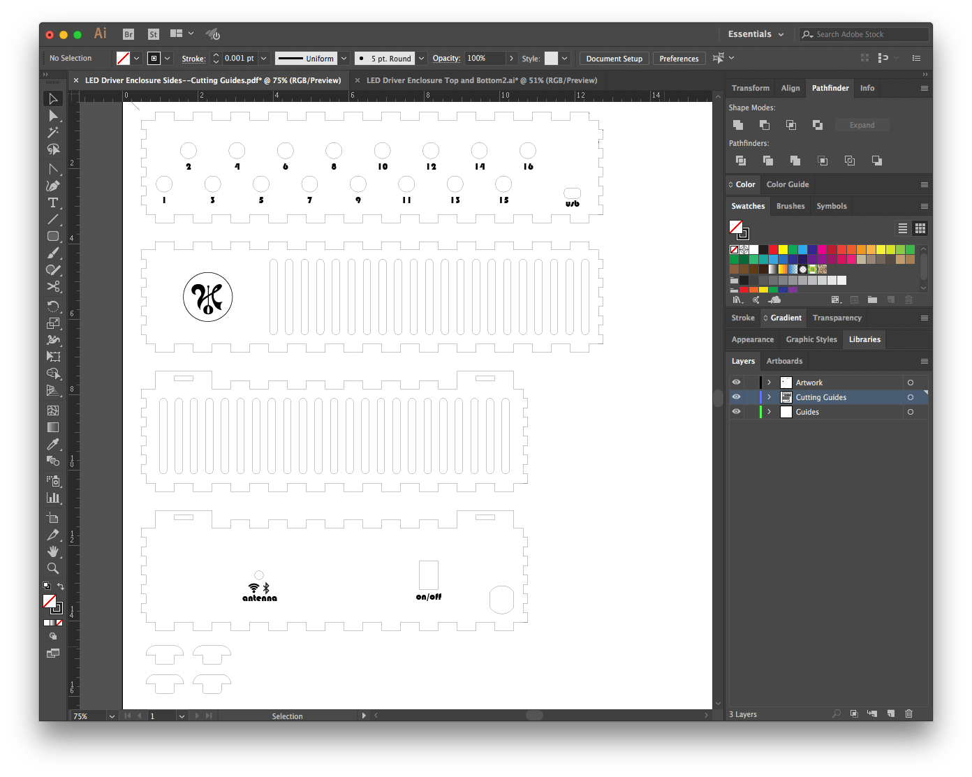
If you look closely, you may notice a few important details. First, the sides and the top and bottom were in separate files. This was because I planned to make the sides out of 1/8″ thick acrylic and the top and bottom out of 1/4″ acrylic. I wanted the bottom in particular to be thicker because I planned to fasten some of the components to it, like the power adapter and the power distribution bus bars. It needed to be thick enough that I could tap screw holes and not crack or bend.
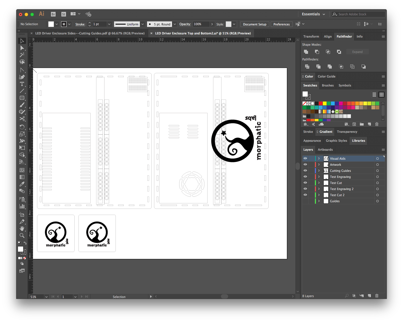
Second, you may notice that I put the artwork to be etched and the shapes to be cut out on different layers. That’s because when you “print” the design using the laser cutter, you have to hide the cutting lines when you etch, and hide the images to be etched when you cut. I also had a layer that contained the outlines of some of the internal components just for reference. I used a set of digital calipers to get the exact dimensions of the power adapter, its vents, and other items to go inside the box.
Third, you may have noticed a couple of extra squares with my logo in them at the bottom of the file with the top and bottom designs. That was because I’d never cut through 1/4″ acrylic before and I didn’t know the appropriate power settings. I also had never used the etching feature before. These pieces at the bottom gave me an opportunity to practice both cutting and etching before I cut out the actual top and bottom. This proved to be critical, and I probably would have ruined en entire sheet of acrylic if I hadn’t had a couple of opportunities to practice first. And I got a couple of cool coasters out of it!
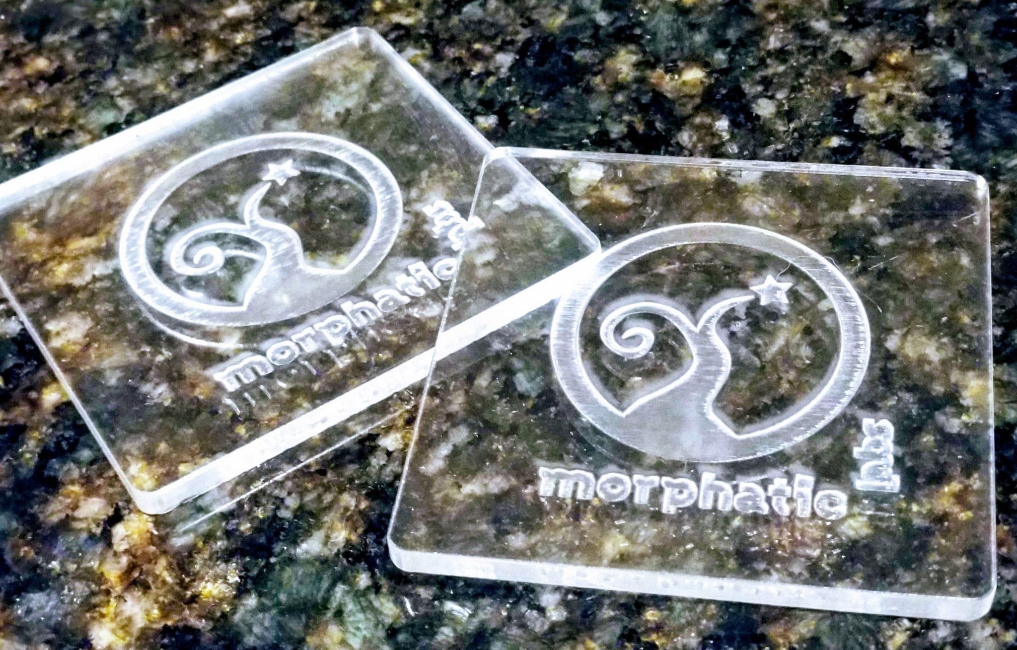
Morphatic Coasters!
As I was preparing to do the laser cutting, I was very happy to have the video I made of one of my former students (Timothy Moore) who is an expert with the laser cutter and amazingly patient and good at explaining things.
It turns out that when you’re cutting through the 1/4″ acrylic (actually it’s 0.22″, not quite 1/4″), it worked best when you set the laser to make 3 passes at 100% power and 40% speed. I still had some scorch marks, but I think next time I may be able to get rid of those if I place something between the acrylic and the grate that is underneath it. I also found that the laser didn’t cut as well in all areas of the acrylic sheet. I had to redo some of the cuts, and press some of them out with a screwdriver. All in all though, I was fairly pleased with the result. It’s not perfect, but it probably won’t bother me because the box will spend the majority of its life sitting above the ceiling tiles of my office where nobody can see it.
The Materials
As I mentioned, the box itself was made of acrylic. I bought two sheets of 18×24″ acrylic, one was 0.22″ and the other (I thought!) was 1/8″. I later figured out that the thinner sheet was actually less than 1/8″, but stupid me, that was the one thing I neglected to measure. Fortunately, it didn’t seriously impact the assembling of the box. Together, the acrylic sheets cost about $40 at a local hardware store.
Power Distribution Bus Bars from AdaFruit
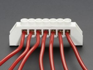
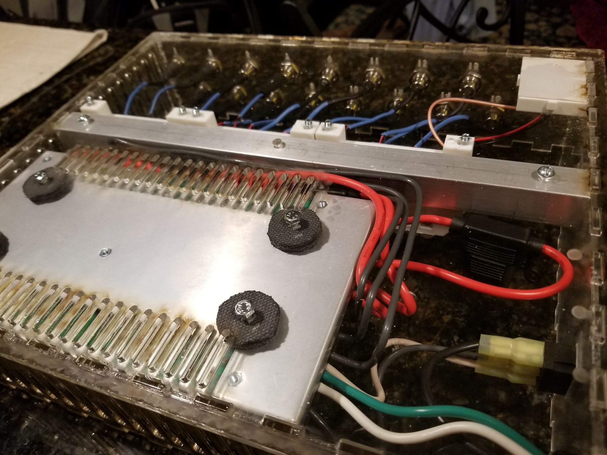
Stealing from Phil Burgess’ design, I used three pairs of distribution bus bars from AdaFruit. Since the perimeter of my office is about 15m, and since it is recommended that power be distributed about every meter, that means I’m going to have 16 cables running from my power distribution box (at the center of the room, over the ceiling) out to my LED strips (on the perimeter, near the ceiling). Each distribution bus can accommodate 7 wires, which means 1 that provides power, and 6 that draw power. That means 3 pairs of bus bars, which will be able to handle all 16 wires, plus one more for the microcontroller. (Yes, I realize that I could run multiple wires into the same terminal, but the bus bars were cheap ($2 each!) and I thought it would be cooler with more.)
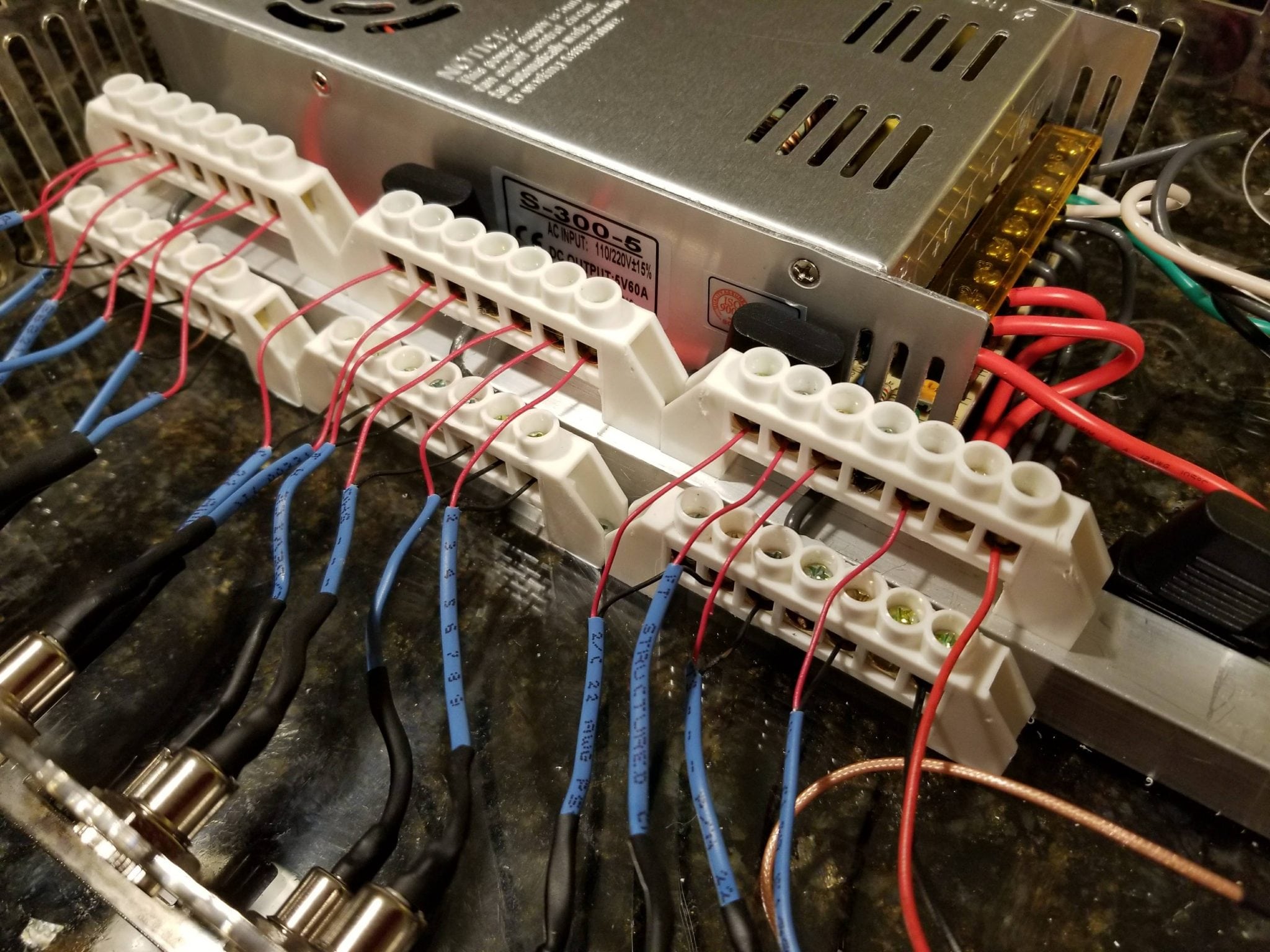
Parallel Rows of Bus Bars, One Elevated on an Aluminum Rod
In order to save space and also to allow the pairs of bus bars to be close to one another, I elevated one of the rows on a 3/4″ square piece of aluminum tubing. Originally, I wanted to use a 1″ piece of square acrylic rod, but that was too hard to find. The coolest thing (for me) about this part of the design was that I got to tap holes for screws for the first time in my life. There’s something deeply satisfying about tapping a screw hole and having the screws threaded perfectly into it. (Okay, I realize after I wrote that how Freudian it sounds. Get your mind out of the gutter!) The aluminum cost about $11 for a 3′ piece, of which I only really needed about 12″.
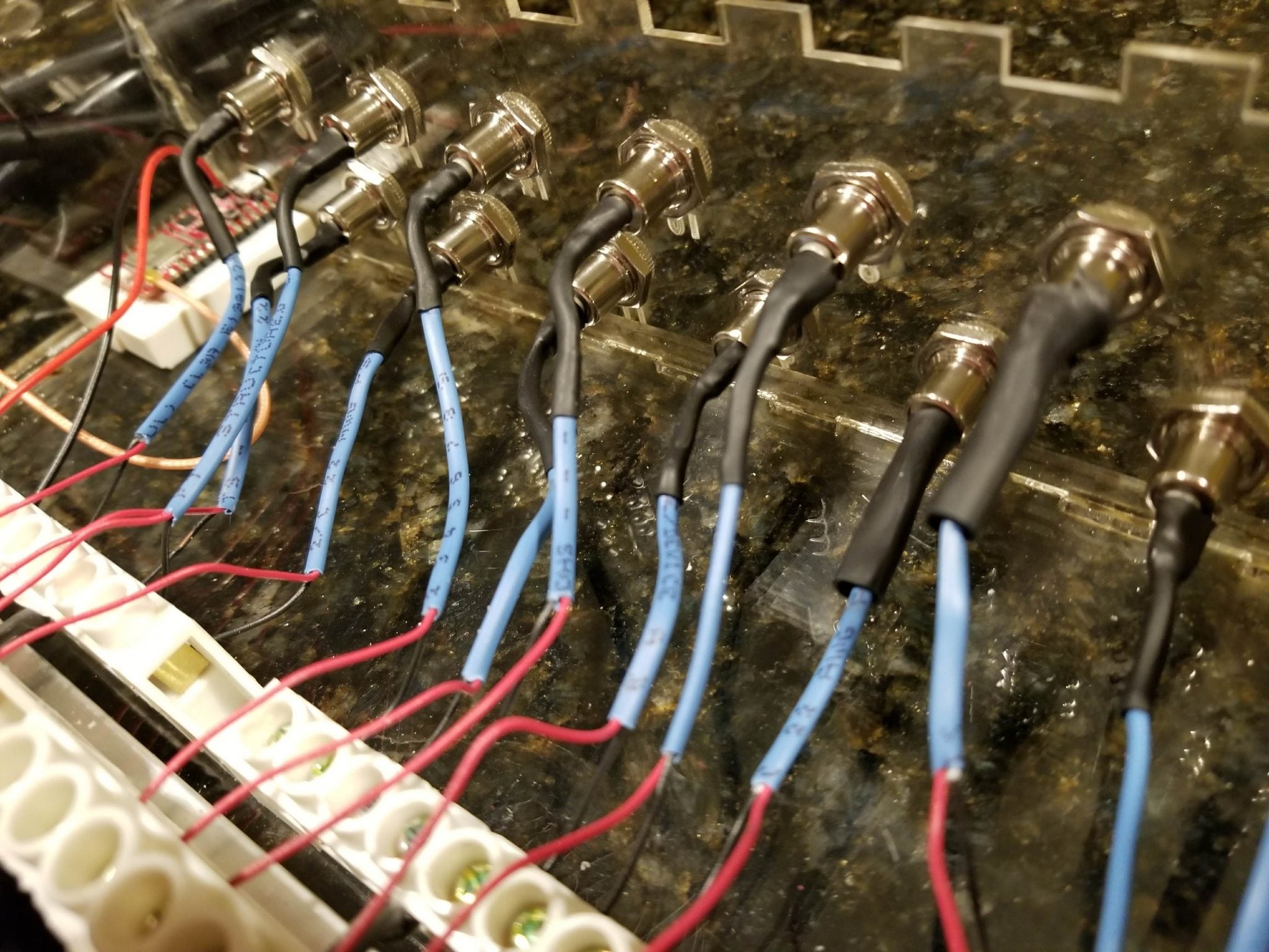
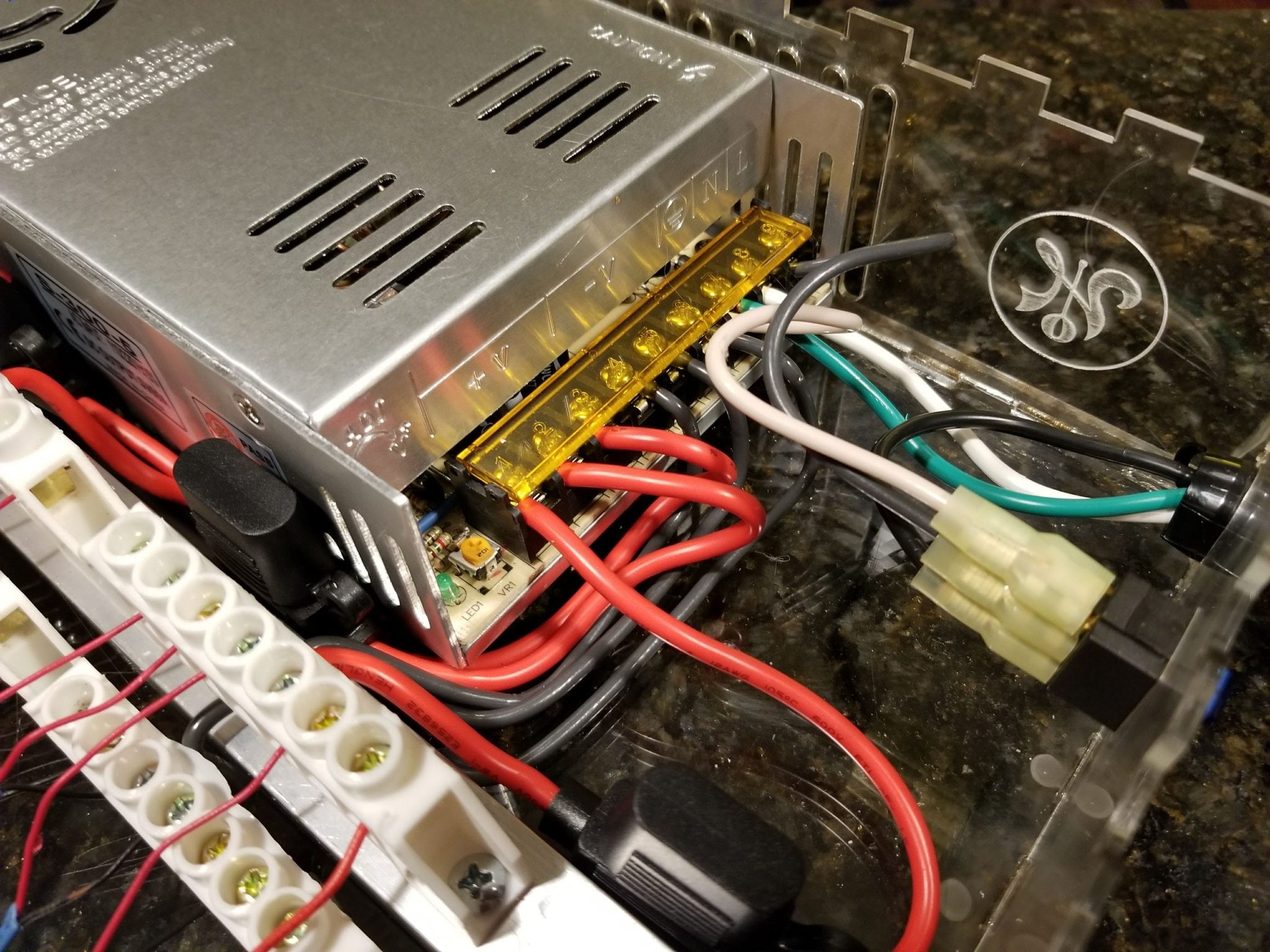
At this point, I realized that if I had 16 cables coming out of the enclosure stretching to all corners of the room, working with the box would quickly become a mess of tangled wires. I decided to make the design more modular by making the power lines “pluggable” with barrel connectors like the ones below:
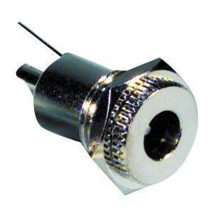

Not only would this make the wires cleaner and easier to organize, but it would make setting up the system much simpler and give me more options for installation. So even though it was $2 for each pair of connectors (and I bought 20 pairs, even though I technically only needed 16), it was very much worth the extra expense. These connectors have to be soldered and I’m glad I bought extras because it took a little while to figure out the best way to do the soldering. Here are some videos that I made demonstrating the process:
I am a super noob when it comes to soldering. If anyone has any suggestions on how I might do this better, please let me know in the comments.
The Microcontroller
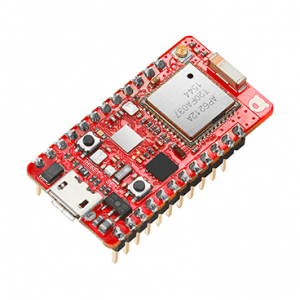
RedBear Duo WiFi + BLE Microcontroller
I’m using a RedBear Duo as the microcontroller for this project. This is a WiFi + Bluetooth Low Energy (BLE) device that has 2MB of flash memory and has plenty of pinouts available for adding on other sensors later on. I got mine from Particle which is one of my favorite vendors for prototyping IoT devices. Particle provides a web-based interface that you can use to program your devices once they are connected to the Internet. I’ll write a future post on how to write the code needed to control the light shows. The good thing is that they operate on the same 5V power supply that the LEDs run on and they have support for connecting to Enterprise Wi-Fi, which is necessary for connecting to the network at my office. These microcontrollers run about $25 each and you can get them with the headers pre-soldered which is convenient.
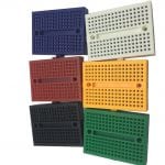
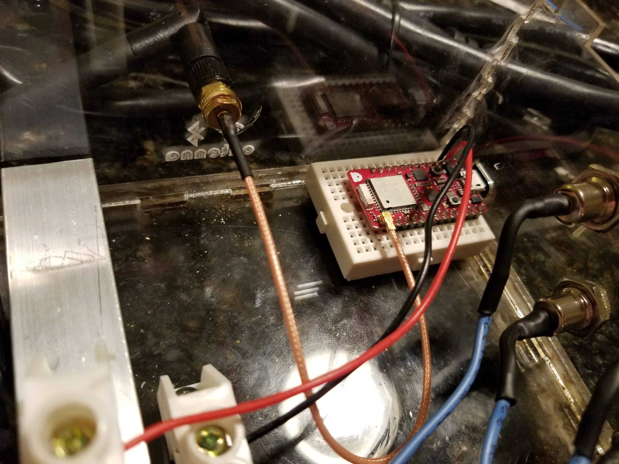
Phantom YoYo Mini Breadboard
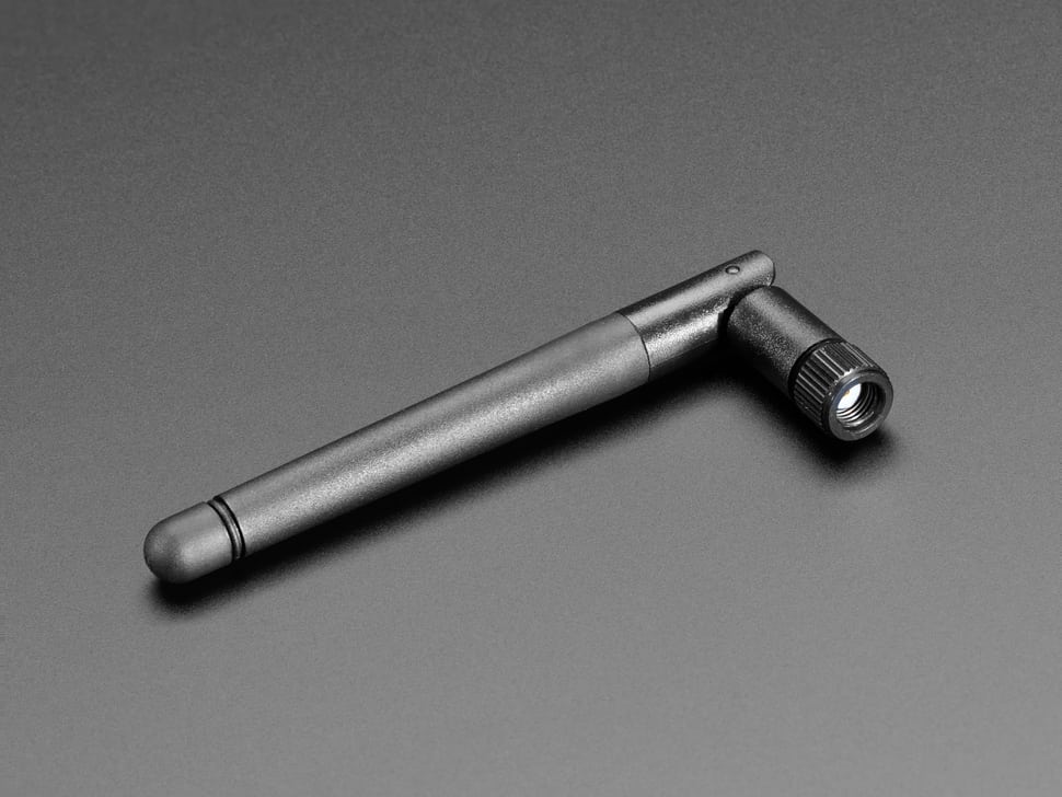
To mount the Duo, I picked up some of these Phantom YoYo mini breadboards. You can get six of them for $6 from Amazon. These little guys are tiny–1.4″ x 1.8″–and they come with adhesive already on the bottom, so it was super easy to mount. I also got an external RF antenna ($7) and a little pigtail adapter ($4) to connect it to the RedBear from AdaFruit. Although I may not need them, I was concerned that the RedBear might have a difficult time connecting to Wi-Fi and/or Bluetooth signals from inside the enclosure and above the ceiling tiles. I figured this would give me extra insurance that all the signals could be received.

Putting It All Together
In addition to all of the stuff I just listed, I also had to buy some screws and some heat shrink tubing which brings the total cost for this phase of the project to about $150. Add that to the $85 I spent on the AC adapter and cables, and I’m up to $235 so far for this project, and I haven’t even bought the LEDs yet! Considering all the fun I’m having, this feels like a bargain to me. I’m also pretty excited to see what my new office will look like once these things are in action.
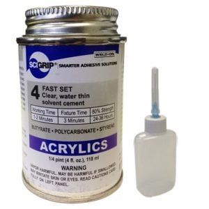
Weld-On 4 Acrylic Cement
Anyway, I used Weld-On 4 acrylic adhesive to glue the sides and bottom of the enclosure together. A can of this costs about $7 from Amazon, but I didn’t have to buy any because I already had a can that I got for the bubble tube project. You have to be careful with this stuff because wherever you drip it on your acrylic it will leave a mark. It basically melts the acrylic on contact. I sets up very quickly and forms a really strong bond, however, so it’s absolutely the right stuff for the job. I recommend doing this part of the job outside because the fumes from the acetone can be pretty intense.
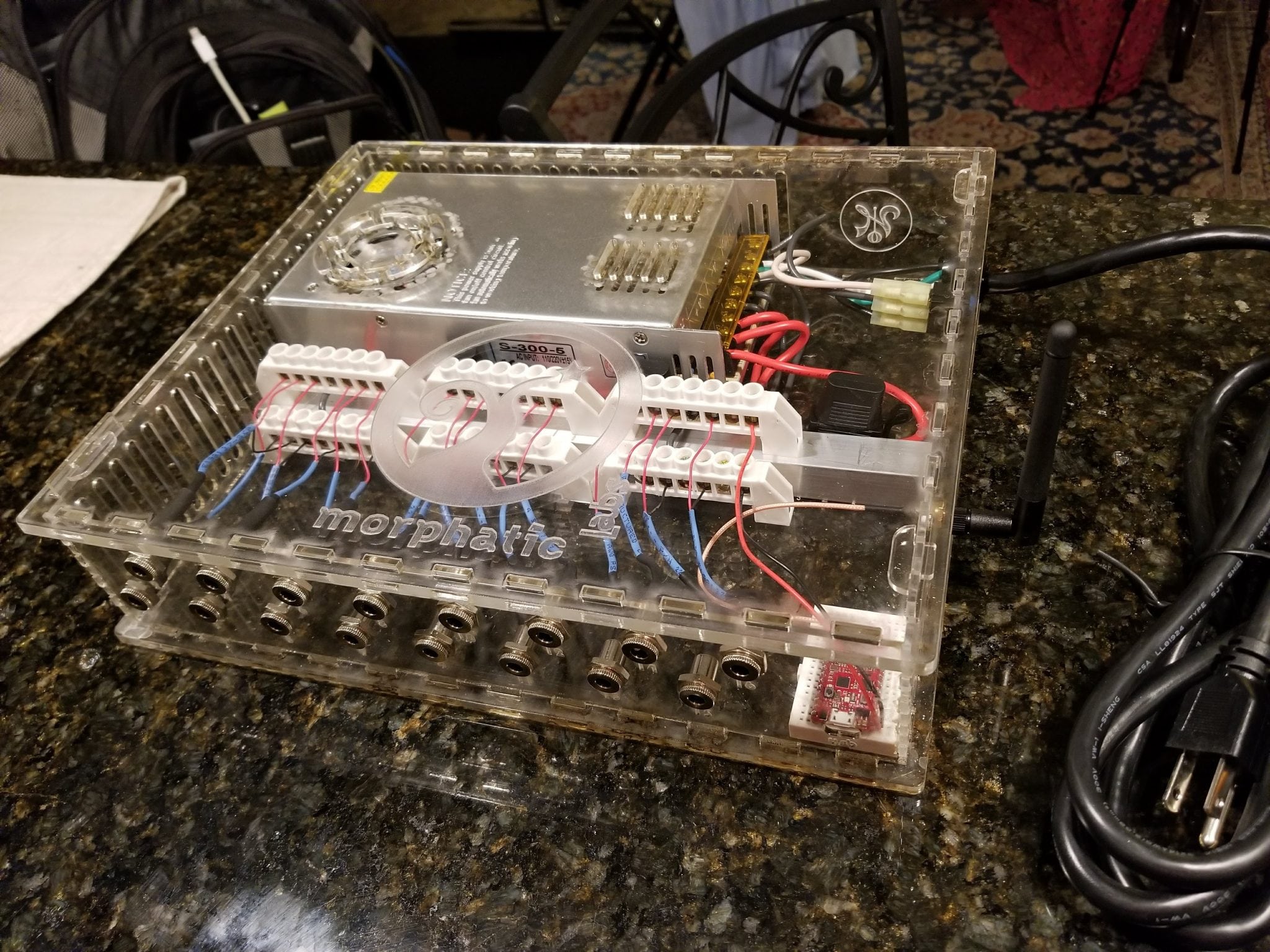
At the end of the day, I was pretty happy with the final product. Here is a gallery of photos of the finished power distribution enclosure:


Conclusion
I’m still waiting for my LED strips to arrive (I ordered them from China). In my next post, I’ll show how I tested out all the electrical connections on the box, and dive into programming the RedBear Duo. I’m getting really excited about seeing this installed and working in my office, but I know it’s probably going to be another couple of weeks before I have a chance to complete it all. Stay tuned!
WTF??? Where is the result of your work? I Don’t wanna waste time, if result looks like my grandma’s poo…Would be nice to see some nice interior pics mate!
Unless your grandma has psychedelic poo, I promise you it looks better. Glad you’re excited to see it. I haven’t had the time to get good images that will do it justice, yet. In the meantime, here’s a crappy video I took with my cell that will give you an idea: https://photos.app.goo.gl/eZjXZrPcY5LCrNzE7 Thanks for your patience!